Introduction
Infrared technology addresses a wide variety of wireless applications. The main areas are sensing and remote controls. In the electromagnetic spectrum, the infrared portion is divided into three regions: near infrared region, mid infrared region and far infrared region.
The wavelengths of these regions and their applications are shown below.
Near infrared region — 700 nm to 1400 nm — IR sensors, We would like to express our sincere thanks towards volunteer researchers who devoted their time and knowledge in the implementation of this project.
Mid infrared region — 1400 nm to 3000 nm — Heatsensing
Far infrared region — 3000 nm to 1 mm — Thermalimaging
The frequency range of infrared is higher than microwave and lesser than visible light.
For optical sensing and optical communication, photo optics technologies are used in the near infrared region as the light is less complex than RF when implemented as a source of signal. Optical wireless communication is done with IR data transmission for short range applications.
An infrared sensor emits and/or detects infrared radiation to sense its surroundings.
The working of any Infrared sensor is governed by three laws: Planck’s Radiation law, Stephen – Boltzmann law and Wien’s Displacement law.
Planck’s law states that “every object emits radiation at a temperature not equal to 00K”. Stephen
– Boltzmann law states that “at all wavelengths, the total energy emitted by a black body is proportional to the fourth power of the absolute temperature”. According to Wien’s Displacement law, “the radiation curve of a black body for different temperatures will reach its peak at a wavelength inversely proportional to the temperature”.
The basic concept of an Infrared Sensor which is used as Obstacle detector is to transmit an infrared signal, this infrared signal bounces from the surface of an object and the signal is received at the infrared receiver.
sed There are five basic elements used in a typical infrared detection system: an infrared source, a transmission medium, optical component, infrared detectors or receivers and signal processing. Infrared lasers and Infrared LED’s of specific wavelength can be used as infrared sources. The three main types of media used for infrared transmission are vacuum, atmosphere and optical fibers. Optical components are used to focus the infrared radiation or to limit thespectral response.OpticallensesmadeofQuartz, Germanium and Siliconareutofocustheinfra radiation. Infrared receivers can be photodiodes, phototransistors etc. some important specifications of infrared receivers are photosensitivity, detectivity and noise equivalent power. Signal processing is done by amplifiers as the output of infrared detector is very small.
List of components

9v battery
Zero PCB
LM358 Microcontroller
Resistors
IR sensor
Receiver
Buzzer
10k variable resistor
LED Light
Components Description
PCBConnection
A zero printed circuit board, or PCB, is used for Electronics and Communication support and electrically connect electronic components using conductive pathways, tracks or signal traces etched from copper sheets laminated onto a non-conductive substrate.
The PCB is printed circuit board having circuit made with cooper layer on the plate there are various steps to design a PCB for that the basic thing required is circuit. So, the circuits required for the system.
Resistor:-
A resistor is a passive two-terminal electrical component that implements electrical resistance as a circuit element. The current through a resistor is in direct proportion to the voltage across the resistor's terminals. Thus, the ratio of the voltage applied across a resistor's terminals to the intensity of current through the circuit is called resistance.
V= IR
where I is the current through the conductor in units of amperes, V is the potential difference measured across the conductor in units of volts, and R is the resistance of the conductor in units of ohms. More specifically, Ohm's law states that the R in this relation is constant, independent of the current.
38
Resistors are common elements of electrical networks and electronic circuits and are ubiquitous in electronic equipment. Practical resistors can be made of various compounds and films, as well as resistance wire (wire made of a high-resistivity alloy, such as nickel-chrome).
Resistors are also implemented within integrated circuits, particularly analog devices, and can also be integrated into hybrid and printed circuits.
RESISTOR

IR LED:-
An IR LED, also known as IR transmitter, is a special purpose LEDthat transmits infrared rays in the range of 760 nm wavelength. Such LEDs are usually made of gallium arsenide or aluminum gallium arsenide. They, along with IR receivers, are commonly used assensors.

IR LED
Resistors are also implemented within integrated circuits, particularly analog devices, and can also be integrated into hybrid and printed circuits.
not, unlike a common LED. To overcome this problem, the camera on a cell phone can be used. The camera can show us the IR rays being emanated from the IR LED in a circuit.
Photodiode:-
A photodiode is a type of photo detector capable of converting light into eithercurrent or voltage, depending upon the mode of operation. The common, traditional solar cell used to generate electric solar power is a large areaphotodiode.

Photodiode
Photodiodes are similar to regular semiconductor diodes except that they may be either exposed (to detect vacuum UV or X-rays) or packaged with a window or optical fiber connection to allow light to reach the sensitive part of the device. Many diodes designed for use specifically as a photodiode use a PIN junction rather than a p-n junction, to increase the speed of response. A photodiode is designed to operate it.
PRESET:-
A preset is a three legged electronic component which can be made to offer varying resistance in a circuit. The resistance is varied by adjusting the rotary control over it. The adjustment can be done by using a small screw driver or a similar tool. The resistance does not vary linearly but rather varies in exponential or logarithmic manner. Such variable resistors are commonly used for adjusting sensitivity along with asensor.
The variable resistance is obtained across the single terminal at front and one of the two other terminals. The two legs at back offer fixed resistance which is divided by the front leg. So whenever only the back terminals are used, a preset acts as a fixed resistor. Presets are specified by their fixed value resistance.
PRESET
LM358:-
The LM358 is a low power dual operational amplifier integrated circuit originally introduced by National Semiconductor.[1] It is used in detector circuits.
The abbreviation LM358 indicates an 8-pin integrated circuit, comprising two operational amplifiers at low power. The LM358 is designed for general use as amplifiers, high-pass filters, low band pass filters, and analog adders.

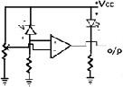
Circuit diagram

Circuit description
It consists of an IR LED, a photodiode, a potentiometer, an IC Operational amplifier and an LED.
IR LED emits infrared light. The Photodiode detects the infrared light. An IC Op – Ampis used as a voltage comparator. The potentiometer is used to calibrate the output of the sensor according to therequirement.
When the light emitted by the IR LED is incident on the photodiode after hitting an object, the resistance of the photodiode falls down from a huge value. One of the input of the op – amp is at threshold value set by the potentiometer. The other input to the op- amp is from the photodiode’s series resistor. When the incident radiation is more on the photodiode, the voltage drop across the series resistor will be high. In the IC, both the threshold voltage and the voltage across the series resistor are compared. If thevoltage
across the resistor series to photodiode is greater than that of the threshold voltage, the output of the IC Op – Amp is high. As the output of the IC is connected to an LED, it lightens up. The threshold voltage can be adjusted by adjusting the potentiometer depending on the environmental conditions.
The positioning of the IR LED and the IR Receiver is an important factor. When the IR LED is held directly in front of the IR receiver, this setup is called Direct Incidence. In this case, almost the entire radiation from the IR LED will fall on the IR receiver. Hence there is a line of sight communication between the infrared transmitter and the receiver. If an object falls in this line, it obstructs the radiation from reaching the receiver either by reflecting the radiation or absorbing theradiation.
Block diagram

Explanation:-
The IR sensor will make the high frequency beam of 5 kHz with the help of 555timer which is set to astable multivibrator mode at the transmitter section.
The IR sensor will produce the high frequency beam which is received by the photo resistor at the receiver section. This frequency will be in one phase when there is no interruption between the IR sensor and photo transistor. Total circuit will not give any output in this phase. When there is an interruption between IR sensor and photo transistor, the beam produced by the IR sensor will be in different phase. This different phase will be immediately detected by the photo resistor and make the 555 timer to give alarm through speaker.
When there is no intrusion, the photo transistor will make the pin2 high of 555timer which is set in monostable mode, and there will be no output given in this configuration. When there is intrusion, the pin 2 of monostable timer is made low which will make the alarm to alert. The alarm time depends on the capacitor C1 and variable resistor POT.
Principle of working
sensor: the main concept of IR sensor is to produce a beam of infrared light (whose wave wavelength is longer than visible rays and shorter than microwaves, in normal infrared wave length should be greater than 6µm). IR sensors are based on three different laws they are planks radiation law, Stephan Boltzmann law and Wien’s displacement law.
Planks Radiation Law states that the energy of electromagnetic radiation is confined to indivisible packets (quanta), each of which has energy equal to the product of the Planck constant and the frequency of the radiation (planks constant = 6.62606957 × 10⁻³⁴ m2 kg /s).
Stephan Boltzmann Law states that total energy radiated per unit on a black body using all wavelengths per unit time J* is directly proportional to the fourth power of the black body’s thermodynamic temperature T:

Wien’s Displacement Law: the wavelength of maximum emission of any body is inversely proportional to its absolute temperature (measured in Kelvin). As a result, as the temperature rises, the maximum (peak) of the radiant energy shifts toward the shorter wavelength (higher frequency and energy) end of the spectrum.
Peak intensity occurs at this wavelength ƛ =(0.0029 meter.K)/Temperature in Kelvin
In IR sensor the infrared source and transmission of infrared are two important parts. In infrared source, there are different sources like black body radiators, tungsten lamps, silicon carbide in IR sensors. They will use infrared wavelength LED as infrared source. In transmission media it will be different like air, optical fiber etc.
Photo Transistor: Photo transistors are the detectors of IR radiation or any photo radiation. They will convert this IR radiation into current or voltage.
Working :-
The principle of an IR sensor working as an Object Detection Sensor can be explained using the following figure. An IR sensor consists of an IR LED and an IR Photodiode; together they are called as Photo – Coupler or Opto – Coupler.

When the IR transmitter emits radiation, it reaches the object and some of the radiation reflects back to the IR receiver. Based on the intensity of the reception by the IR receiver, the output of the sensor is defined.
How to use:-
To use sensor you only need power the sensor by connect two wires +5V and GNDto Pin’1’ & Pin’2’ respectively. Leave middle output pin for interfacing with any controller. When LED is off the output isLow.
Bring any object nearby the Sensor and the LED will lit up and output becomes High. The output is active High and can be given directly to microcontroller or usingcurrent limiting 1K resistor in series for interfacingapplications.

When their is "NO BOJECT" or "DARK OBJECT" present, than Transmitted IR will not reflect back to RX(Photo Diode) and Vout (Output) will be LOW.

When "LIGHT -COLOR OBJECT" is present, than Transmitted IR will reflect back andVout (Output) will be HIGH.
Proximity IR Sensor Module & Microcontroller, through which it is interface, should have common GND & VCC +5V. Current limiting resistor of 220ohm to 1K can be used to connect Vout pin of Proximity IR Sensor Module with any digital I/O pin of controller.

Advantages and Disadvantages
Advantages :-
➨It can be used in very harse environment having irregular heat cycles (Active Motion Sensor).
➨It has more lifespan which is about 100000 Hrs (Active type).
➨It detects motion in light and dark conditions reliably in indoors. (Passive motion sensor)
➨It helps in providing security by detecting suspicious movement.
➨It is easy to install motion sensors.
DISADVANTAGES :-
➨Radio frequency at high power is harmful for humans (active type).
➨Radio frequency in microwave range do not penetrate metal objects (active type).
➨Passive motion sensors do not operate above temperature of 350C.
➨Passive sensor type works in LOS (Line of Sight) and does not work in non-LOS regions.
➨Passive type is insensitive to very slow motion of the object.
➨Passive Infrared (PIR) Sensor can detect human being within approx. 10 meters range.
➨Any kind of moving object can trigger the PIR sensor type.
Result
The main idea of this proeject is to reduce the wastage of electricity.
For this purpose IR’s and LDR's used as a sensors.
The street light corresponding to that IR will Switch ON automatically when Vehicle passes.
Conclusion
There are five basic elements used in a typical infrared detection system: an infrared source, a transmission medium, optical component, infrared detectors or receivers and signal processing. Infrared lasers and Infrared LED’s of specific wavelength can be used as infrared sources. The three main types of media used for infrared transmission are vacuum, atmosphere and optical fibers. Optical components are used to focus the infrared radiation or to limit the spectral response. Optical lenses made of Quartz, Germanium and Silicon are u to focus the infrared radiation. Infrared receivers can be photodiodes, phototransistors etc. some important specifications of infrared receivers are photosensitivity, detectivity and noise equivalent power. Signal processing is done by amplifiers as the output of infrared detector is very small.
Applications
Motion detectors can be used as an intruder alarm in home, offices, banks, shopping malls etc.
They can be used as counting machines, automatic light control etc.
They can be used in energy efficient systems, home automation system and control systems.
ProximitySensor
Object Neardetection
Tachometer (Measure FanSpeed)
Obstacle DetectorSensor
Line/Wall FollowerSensor
Objectcounteroverconveyerbelt
Intruder alarms
Automatic ticket gates
Entry way lighting
Security lighting
Automated sinks/toilet flusher
Hand dryers
Automatic doors
Reference
Heath, Steve (2003). Embedded systems design. EDN series for design engineers (2 ed.). Newnes. pp. 11–12. ISBN9780750655460
How Does a Motion Sensor Work? -eHow
How does a motion detector work? –Alarm Grid
What is a Motion Sensor? - Digikey
Motion Detector- Vernier

No comments:
Post a Comment